Transcription
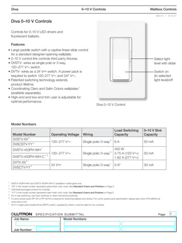
Diva0–10 V ControlsWallbox Controls369147j 1 02.19.21Diva 0–10 V ControlsControls for 0–10 V LED drivers andfluorescent ballasts.Features Large paddle switch with a captive linear-slide controlfor a standard designer-opening wallplate. 0–10 V control link controls third party fixtures. DVSTV- wires as single pole or 3-way,120–277 V switch. DVTV- wires as a 24 V- switch. A power pack isrequired to switch 120–277 V and 347 V . Patented switching technology extendsproduct lifetime. Coordinating Claro and Satin Colors wallplates 1(available separately). High-end and low-end trim user is adjustable foroptimal performance.Select lightlevel with sliderSwitch on(to selectedlight level)/offDiva 0–10 V ControlModel NumbersModel Number2DVSTV-XXDVSCSTV-YY 4DVSTV-453PH-WHOperating VoltageWiring120 –277 V Single pole / 3-way5120 –277 V Single pole / 3-way524 V-Single pole / 3-way71DVSTV-453PH-WH-C1, 3Load SwitchingCapacity0–10 V SinkCapacity8A50 mA450 W3.75 A (120 V )1.62 A (277 V )50 mA0 A630 mA2DVTV-XX4DVSCTV-YY1234567DVSTV-453PH-WH and DVSTV-453PH-WH-C available in white gloss only.“XX” in the model number represents gloss finish color code. See Standard Colors and Finishes on Page 5.Clamshell packaged product for Canada.“YY” in the model number represents satin finish color code. See Standard Colors and Finishes on Page 5.For 3-way switching, use Claro switches or other mechanical switches.A Lutron power pack (PP-DV or PP-347H) is required for switching ballasts and drivers. For Lutron power pack specification, please see Lutron P/N 369544 V- single-pole double-throw (SPDT) switch, supplied by others, must be rated for dry contacts.Job Name:Job Number:S P E C I F I C AT I O N S U B M I T TA LModel Numbers:Page1
Diva0–10 V ControlsWallbox Controls369147j 2 02.19.21SpecificationsDVSTV- ModelsRegulatory Approvals cULus Listed NOMPowerOperating Voltage120–277 V 50/60 HzEnvironment For indoor use only. Ambient operating temperature: 32 F to 104 F(0 C to 40 C), 0% to 90% humidity,non-condensing.Application RequirementsOutput Ratings Switch rating of 8 A. 0–10 V control link for 50 mA maximum output(sink only). No derating required if ganged. Night light not available. Always consult local wiring codes.0–10 V Control Link 0–10 V control link is Class 1. Controls up to 25 ballasts or drivers (IEC 60929 AnnexE.2 requires the ballast / driver to limit the current drawto 2.0 mA maximum). WarrantyPerformance Power pack cannot be used with DVSTV- models. Works with all ballasts and drivers that provide acurrent source compliant to IEC 60629 Annex E.2,and whose inrush current does not exceed NEMA410standards for electronic ballast / driver loads of 8 Asteady state current. Adjustable high-end and low-end trim for optimaldimming performance. Power failure memory: should power be interrupted,the control will return to its previously set level prior tothe interruption when power is restored. Captive linear slider. Precise color matching.Job Name:Job Number:S P E C I F I C AT I O N S U B M I T TA LModel Numbers:Page2
Diva0–10 V ControlsWallbox Controls369147j 3 02.19.21Specifications (continued)DVSTV-453PH-WH ModelRegulatory Approvals cULus Listed NOMPowerOperating Voltage120–277 V 50/60 HzEnvironment For indoor use only. Ambient operating temperature: 32 F to 104 F(0 C to 40 C), 0% to 90% humidity,non-condensing.Application RequirementsOutput Ratings Switch rating of 450 W. 0–10 V control link for 50 mA maximum output(sink only). No derating required if ganged. Night light not available. Always consult local wiring codes.0–10 V Control Link 0–10 V control link is Class 1. Controls up to 25 ballasts or drivers (IEC 60929 AnnexE.2 requires the ballast / driver to limit the current drawto 2.0 mA maximum). WarrantyPerformance Power pack cannot be used with DVSTV- models. Works with all ballasts and drivers that provide acurrent source compliant to IEC 60629 Annex E.2,and whose inrush current does not exceed NEMA410standards for electronic ballast / driver loads of 8 Asteady state current. Adjustable high-end and low-end trim for optimaldimming performance. Power failure memory: should power be interrupted,the control will return to its previously set level prior tothe interruption when power is restored. Captive linear slider. Precise color matching.Job Name:Job Number:S P E C I F I C AT I O N S U B M I T TA LModel Numbers:Page3
Diva0–10 V ControlsWallbox Controls369147j 4 02.19.21Specifications (continued)DVTV- and DVSCTV- ModelsPowerEnvironmentOperating Voltage24 V- 100 mAOutput Ratings Power pack required for load switching. Power pack israted for 16 A. 30 mA maximum output (sink only).0–10 V Control Link 0–10 V control is Class 2. Controls up to 15 ballasts or drivers (IEC 60929 AnnexE.2 requires the ballast / driver to limit the current drawto 2.0 mA maximum).Performance For indoor use only. Ambient operating temperature: 32 F to 104 F(0 C to 40 C), 0% to 90% humidity,non-condensing.Application Requirements No derating required if ganged. Night light not available. Always consult local wiring codes.Warranty For 120–277 V installations switching more than8 A, use DVTV- with Lutron power pack (PP-DV). SeeLutron P/N 369544. For 347 V installations, use DVTV- with Lutron powerpack (PP-347H) See Lutron P/N 369544. Works with all ballasts and drivers that provide acurrent source compliant to IEC 60629 Annex E.2. Adjustable high-end and low-end trim for optimaldimming performance. Power failure memory: should power be interrupted,the 0–10 V- signal will return to its previously set levelprior to the interruption when power is restored. Captive linear slider. Precise color matching.Job Name:Job Number:S P E C I F I C AT I O N S U B M I T TA LModel Numbers:Page4
Diva0–10 V ControlsWallbox Controls369147j 5 02.19.21Dimensions2.75 in(70 mm)4.69 in(119 mm)2.94 in(75 mm)0.30 in(7.6 mm)1.31 in(33 mm)Standard Colors and FinishesGloss Finishes*Satin Colors*Add color suffix to model numberExample: DVSTV-WHWH WhiteAdd color suffix to model numberExample: DVSCTV-SWSWSnowMNTPTaupeBIESEggshellPDHTHot MRPLPlumSITCTerracottaBGGBGreen BriarGSMSMocha StoneSTDSDesert StoneLSIVALLAGRBRBLIvoryAlmondLight AlmondGrayBrownBlack* DVSTV-453PH-WH and DVSTV-453PH-WH-C available in white gloss only.Job Name:Job Number:S P E C I F I C AT I O N S U B M I T TA LModel oneGoldstoneStoneLimestoneFor the latest color offerings.
Diva0–10 V ControlsWallbox Controls369147j 6 02.19.21High-End and Low-End AdjustmentsDVSTV- ModelsAll ModelsFront ViewBottom ViewMaximum Light Level(High-End) TrimMinimum Light Level(Low-End) TrimDVTV- and DVSCTV- ModelsSide ViewMaximum Light Level(High-End) TrimJob Name:Job Number:S P E C I F I C AT I O N S U B M I T TA LModel Numbers:Page6
Diva0–10 V ControlsWallbox Controls369147j 7 02.19.21Wiring DiagramsDVSTV- / DVSCSTVSingle Pole WiringLine/HotBlackRedSwitchedHotViolet ( )Violet ( )Pink ‡ (-)Pink ‡ (-)Red / White0–10 V- Ballast / DriverNeutral120–277 V 50/60 HzGroundSwitchedHotViolet ( )Pink ‡ (-)Neutral0–10 V- Ballast / DriverNeutral3-Way WiringLine/Hot***Red*Red /White3-WaySwitch †120–277 V 50/60 HzBlackSwitchedHotViolet ( )Violet ( )Pink ‡ (-)Pink ‡ (-)0–10 V- Ballast / DriverNeutral***GroundGroundSwitchedHotViolet ( )Pink ‡ (-)Neutral0–10 V- Ballast / DriverNeutral* Copper / Black screw terminal** Brass / Gold screw terminal*** Green screw terminal†‡For proper wiring, please refer to installation instructions for 3-way switch.This wire/terminal may be gray on older products or in retrofit applications.Job Name:Job Number:S P E C I F I C AT I O N S U B M I T TA LModel Numbers:Page7
Diva0–10 V ControlsWallbox Controls369147j 8 02.19.21Wiring Diagrams (continued)DVSTV- / DVSCSTV- (continued)4-Way WiringLine/Hot****3-waySwitch †**4-waySwitch †**********GroundGround120–277 V 50/60 HzRedRed /WhiteBlackSwitchedHotViolet ( )Violet ( )Pink ‡ (-)Pink ‡ (-)0–10 V- Ballast/DriverNeutralGroundSwitchedHotViolet ( )Pink ‡ (-)0–10 V- Ballast/DriverNeutralNeutralNote: For 4-way wiring, control must be installed line side or load side. It cannot be installed in the 4-way location.* Copper / Black screw terminal** Brass / Gold screw terminal*** Green screw terminal†‡For proper wiring, please refer to installation instructions for 3-way /4-way switch.This wire/terminal may be gray on older products or in retrofit applications.Job Name:Job Number:S P E C I F I C AT I O N S U B M I T TA LModel Numbers:Page8
Diva0–10 V ControlsWallbox Controls369147j 9 02.19.21Wiring Diagrams (continued)DVTV- and DVSCTV-Dimming With ON/OFF ControlWiring Diagram Using a Power PackSingle Pole WiringClass 2 OnlyNeutralViolet ( )0–10 V- Ballast / DriverPink ‡ (-)Red / WhiteSwitchedHotNeutralViolet ( )Violet ( )Pink ‡ (-)Pink ‡ (-)0–10 V- Ballast / DriverSwitchedHotRedBlueRedRed*GroundPP-DV / PP-347HNeutralWhiteBlackBlack120–277 / 347 V 50 / 60 HzLine / HotGround3-Way WiringClass 2 OnlyNeutralRedBlueViolet ( )Pink‡ (-)Red / WhiteViolet ( )Pink‡ (-)Violet ( )Pink‡ (-)3-waySwitchDVTV Dimmer0–10 V- Ballast / DriverSwitchedHotNeutral0–10 V- Ballast / DriverSwitchedHotRedRedBluePP-DV /PP-347HBlackRedWhiteNeutralBlack347 V 50 / 60 HzLine / Hot* Must use shielded cable with the drain grounded and grounded faceplate/yoke.‡This wire/terminal may be gray on older products or in retrofit applications.Job Name:Job Number:S P E C I F I C AT I O N S U B M I T TA LModel Numbers:Page9
Diva0–10 V ControlsWallbox Controls369147j 10 02.19.21Wiring Diagrams (continued)DVTV- and DVSCTV-Dimming With ON/OFF ControlWiring Diagram Using a Power Pack (continued)4-Way WiringClass 2 Only4-waySwitch3-waySwitchRedBlueViolet ( )Pink‡ (-)Neutral0–10 V- Ballast / Driver SwitchedHotRed / WhiteViolet ( )Pink‡ (-)Violet ( )Pink‡ (-)Neutral0–10 V- Ballast / Driver SwitchedHotDVTV DimmerRedPP-DV /PP-347HBlueBlackRedRedNeutralWhiteBlack347 V 50 / 60 HzLine / HotDimming With ON / OFF Control For Drivers Which Support Dim To OFF CapabilityPower Wiring Not Shown—See Lighting Device For WiringRed/WhiteViolet ( )Violet ( )Pink (-)Pink ‡ (-)‡0–10 V- Ballast / DriverRedBlueViolet ( )Pink ‡ (-)0–10 V- Ballast / DriverThis wiring diagram is used when the fixture / ballast / driver is "dim to OFF" and complies with ANSI C137.1. With this wiring setup, the line voltage power isconstantly supplied to the fixture / ballast / driver and the paddle switch on the Diva dimmer brings the 0–10 V signal to 0 V when in the off position.‡This wire / terminal may be gray on older products or in retrofit applications.The Lutron logo, Lutron, Diva, Claro, and Satin Colors are trademarks or registered trademarks of Lutron Electronics Co., Inc. in the US and/or other countries.All other product names, logos, and brands are property of their respective owners.Job Name:Job Number:S P E C I F I C AT I O N S U B M I T TA LModel Numbers:Page10